« October 2007 | Main | December 2007 »

November 2007 Archives

November 7, 2007

europa_module_factory unveiled

Some results. I've been working up a new framework for authoring HDL modules in Europa, using a simple example component (SPI Slave) as an anchoring point. To present the results, I'll first do a top-down traversal, then dig a bit into the details.

From the top

From the user's point of view, the top level is a simple script, "mk.pl", which invokes the top-level package. This script is not truly a part of the architecture, but it's an easy place to start. Here's the basic call-and-response, at your friendly neighborhood cygwin shell:

[SOPC Builder]$ perl -I common mk.pl

mk.pl:
Missing required parameter 'component'
Missing required parameter 'top'
Missing required parameter 'name'

Usage:
mk.pl [--help]
(Print this help message)

mk.pl --component=<component name> \
        --top=<top level module> \
        --help
(Print sub-package-specific (component::top) help)

mk.pl --component=<component name> \
        --top=<top level module> \
        --name=<top level module name> \
        <component-specific options>
(Create a module of type component::top, with the given name
and options)

A few notes here:

  • "common" is a subdirectory where I've stashed infrastructure perl modules:
    • europa_module_factory.pm: All HDL-module-producing packages derive from this base class.
    • component_utils.pm: You always need one of these. Today it just contains a routine for command-line processing. I expect to throw more stuff in here later.
  • "component" is the overall name of a component (in my example, "spi_slave"). All perl packages for a component are installed in a directory named the same as the component (directory "spi_slave"); all packages are one level down in the hierarchy from the component name (e.g. perl package "spi_slave::control", or "spi_slave/control.pm" in the file system).
  • "top" is the package to invoke as the component top-level. Any sub-package within a component is suitable for top-level invocation, which is handy during development. During ordinary use, there may be several sub-packages which are invoked as the top level.

sub-package-specific help

Here's something cool: component sub-packages must declare their required fields and valid values for those fields. Wouldn't it be handy if sub-package-specific help text were built from that same set of declared required fields? Yes, very handy. Example:

[SOPC Builder]$ perl -I common mk.pl --component=spi_slave \
> --top=spi_slave_mm --help

Allowed fields in package 'spi_slave::spi_slave_mm':
datawidth:
        Data width
        range: [1 .. maxint]
lsbfirst:
        data direction (0: msb first; 1: lsb first)
        range: [0 .. 1]

(By the way, sub-package "spi_slave_mm" is one of the expected top-level packages - it's the SPI Slave component with an Avalon-MM flowcontrol interface.)

How about some help for a less top-level sub-package?

[SOPC Builder]$ perl -I common mk.pl --component=spi_slave \
> --top=fifo --help

Allowed fields in package 'spi_slave::fifo':
datawidth:
        range: [1 .. maxint]
depth:
        allowed values: 1

You can see that this help is less verbose - that's simply because sub-package "fifo" didn't happen to provide descriptions for its fields.

Building an SPI Slave

Help text is swell, but what does a successful component build look like? A few more -I includes are required; a Makefile helps keep things tidy:

[SOPC Builder]$ make
perl \
  -I $QUARTUS_ROOTDIR/sopc_builder/bin \
  -I $QUARTUS_ROOTDIR/sopc_builder/bin/europa \
  -I $QUARTUS_ROOTDIR/sopc_builder/bin/perl_lib \
  -I ./common \
  mk.pl \
          --component=spi_slave \
          --top=spi_slave_mm \
          --name=spi_0 \
          --target_dir=. \
          --lsbfirst=0 --datawidth=8

I've set a name for the top-level HDL file (spi_0), and specified a target directory in which to generate. Parameters "lsbfirst" and "datawidth" are passed along to the chosen subpackage, "spi_slave::spi_slave_mm".

Generator Innards

The basic inner loop of a generator sub-package looks something like this:

# construct an instance of a sub-package module-factory, for example:
my $tx = spi_slave::tx->new({
  lsbfirst => 0,
  datawidth => 13,
});
# ask the module-factory for an HDL instance, and it to the module: 
$module->add_contents(
  $tx->make_instance({
    name => "the_tx",
  }),
);

Besides factory-generated instances, the sub-package will add simple logic of its own to the module.

SPI Slave Results

The new SPI Slave component occupies 32 LEs in my example system (tb_8a), and functions just as the old SPI component did (the old component occupied 40 LEs). The new component is heavily modularized; individual module tend to be very simple. The module hierarchy of the component is in 3 levels:

  • spi_slave_mm
    • spi_slave_st
      • av_st_source
      • av_st_sink
      • control
      • fifo (rx_fifo)
      • fifo (tx_fifo)
      • sync
      • rx
      • tx

The simplicity of this component hides some of the power of the europa_module_factory architecture. It turns out that only a single factory instance is created by each sub-package of the SPI Slave, and in only one case (sub-package "fifo") does an factory deliver more than one HDL instance; in general, though, a single sub-package will create multiple factory instances, which in turn will deliver multiple HDL instances.

By the way, that middle level, spi_slave_st, is a perfectly viable top-level component all on its own, assuming you'd like an Avalon-ST sink and source, rather than an Avalon-MM slave with flow control. This highlights what I believe is a major feature of the architecture: hierarchy comes "for free". Any perl package (and likewise, HDL module) can be instantiated within another. The way is clear to create deeply-nested design hierarchies composed of reusable blocks. It's also possible to build complete systems of components and interconnect, all within a single running perl process. But possibly the most common use of hierarchy will be to add a small amount of functionality to an existing component, by wrapping that component in another layer.

Here's an archive of the component factory modules, spi slave modules and Makefile/build script.

November 14, 2007

avalon_st_error_adapter

An unexpected puzzle came up - a component which seems simple, but turns out to be rather annoying to implement. A good test case, I say. I'll make this quick and brief - the new component files are attached below if you want to dig deeper.

The component's Family/Genus/Species is Adapter/Avalon-ST adapter/Avalon-ST Error Adapter.

Adapter

An adapter, generally speaking, is a simple component which is inserted in between a pair of components of a particular type, to accomplish some sort of conversion. A typical example is the data-width adapter (to allow connection of, say, an Avalon-MM master and slave, or an Avalon-ST source and sink, which happen to have different data widths). A good adapter is fairly simple, does only one thing, and is completely parameterized according to information from the interfaces it connects to.

Avalon-ST Adapter

Adapters of this description are tailored to the particular set of signals supported by Avalon-ST. These adapters understand the specific direction of Avalon-ST signals (e.g. the "data" signal is an output from a source, and an input to a sink; the "ready" signal is an input to a source, and an output from a sink).

Avalon-ST Error Adapter

This adapter does straight-through wiring on all Avalon-ST signals except for one, the "error" signal. All signals other than "error" are required to have the same bit width on both the source and sink which the adapter is connects to. And that's where the regularity ends: the "error" signal is wonderfully free to vary. The source may have no error signal, or a multiple-bit one; likewise on the sink. With mismatched widths, how can the adapter do its job? Well, one more thing about the error signal: each individual bit of the error signal has a "type", which is an arbitrary string, or the special string "other". Given a "type map" for all the source and sink error bits, there are some simple rules for error signal adaptation:

  1. Like-type error bits are directly connected
  2. If the sink has an error bit of type "other", it's driven by the logical OR of any as-yet unconnected source error bits (type "other" or otherwise).
  3. If any undriven sink error bits remain, they are driven with 0.
  4. Any remaining unconnected source error bits are ignored.

Huzzah, a new base class

Since any Avalon-ST adapter will have a mess of same-width signals which wire straight through, and then maybe one signal which needs some special treatment, it makes sense to derive a base class (avalon_st_adapter) from europa_module_factory, from which all Avalon-ST adapters will further derive. This base class calls into a derived class method for doing any special signal handling, then does straight-through wiring on any remaining (non-special) signals. The derived class is concerned only with doing its special job on its special signal(s), and managing any options relevant to the special signal(s).

Command-line args - limited to simple numerals and strings thus far

But that's far too limiting. Here's why: avalon_st_adapter is a component in its own right, though really a silly one. Its generation parameters are a set of signal descriptions (name, width and type) on its "in" (driven by the source) and "out" (driving the sink) interfaces. It's natural to think of these input parameters as a simple pair of hashes, keyed on signal type. But I want to retain the guideline of pure command-line specification of parameters. I could encode those hashes as comma-separated lists of things, to be massaged and processed by a script into proper perl data structures, but that seems like a lot of work. What to do? No problem, I simply pass my hashes in perl syntax on the command line, appropriately escaped, and "eval" does the parsing for me. Validation of these non-scalar fields presents a bit of a nuisance, but nothing that can't be dealt with. For now, I simply validate against the field "type" (HASH, ARRAY, CODE, undef-for-scalar), but nothing stops me from (in the future) defining nested parameter data structures which encode the same sorts of value sets and ranges that I already use for scalar parameters.

To the basic set of port declarations which form avalon_st_adapter's generation parameters, avalon_st_error_adapter adds two more hashes, in which the "in" and "out" interface error bit types are described.

Testing, testing...

Once I had the basic avalon_st_adapter class working, and a skeleton implementation of avalon_st_error_adapter, I found myself doing lots of exploratory refactoring. I worried that I'd break the functionality, which I was happy with. Solution: unit tests. In my case, this means, for each component, a handful of test-case scripts, each of which produces an HDL module, and a top-level test script, "test.sh". After making a change, I run ". test.sh", which runs all the test cases and diffs the output HDL against a set of "known-good" files in a subdirectory. Occasionally, a change is made which does change the output HDL, and for those cases, I carefully examine the new and old files to convince myself that the new HDL file can replace the old known-good one (or note that I've created a new bug, and fix it).

Avalon-ST signal type "error": wonderfully free form

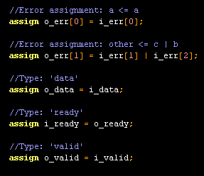
Actually, this is rather an annoying adapter, due to the unconstrained nature of the "error" signal. You'll note that all of the nuisance is concentrated in avalon_st_error_adapter::make_special_assignments().

HDL comments

I went a bit out of my way to produce comments on the adapter assignments, to label the signals and error bit types. Here's a nice ascii block diagram of error adapter test case "3":

avalon_st_error_adapter3.gif

... and here's a snippet of of test case 3's HDL implementation, showing handy assignment comments:

avalon_st_error_adapter3.v.gif

That's it for now. For all my most ardent fans, I'm attaching the new avalon_st_adapter and avalon_st_error_adapter components, along with their test scripts and known-good HDL files. I'm also including the latest version of europa_module_factory, which changed slightly to support the new command-line processing.

components20071114.zip

November 25, 2007

Pulse Measurement Testbench

The heart of an IR receive circuit is the pulse measurement circuit. A single-bit signal goes in, and the length of each input pulse goes out. IR-protocol-specific logic to decode the actual data values being transmitted would work off the sequence of length values coming out of the pulse measurement block. The pulse-measurement circuit itself, though, is protocol-agnostic.

Now, I'm planning to build this pulse-measurement circuit (and later on, the follow-on data decode circuit) in firmware in the f2013. I could drive pulses into the f2013 by aiming an IR remote control at the IR transceiver (as seen in VIII. My Little GP1UE267XK) and pushing various buttons on the remote. That sounds pretty annoying - I'd have to pick up and put down the remote all the time, in between typing, and the resulting pulses would vary in length according to factors beyond my control (as I documented in XIII. WWASD?).

Here's a better idea: I'll build logic in the FPGA to generate precise, reproducible pulse sequences, under control of the host PC. Without moving my hands from the keyboard, I'll download various pulse sequences to the hardware, which in turn will drive the device-under-test (f2013 firmware in active development). If I equip the f2013 and testbench logic with a SPI-to-JTAG bridge (as seen in XIV. Hello, world!), then the f2013 can send its interpretation of the pulse sequence back to the host. A script can compare the f2013's report with what was sent - so - a regression test system is possible.

Here's a top-level block diagram of the system:

block.gif

You can see three basic sub-blocks:

  1. VJI: A virtual-JTAG-interface which provides a FIFO-write interface ("source") and an additional signal, "go".
  2. Pulse Gen: The pulse generator proper. The idea here is that the VJI writes a sequence of values into the pulse generator's internal FIFO (data rate limited by the JTAG interface), then asserts the "go" signal, which initiates processing on the FIFO data at top speed. Data read from the internal FIFO specifies the level and pulse duration on the single-bit output, "out".
  3. f2013: The f2013 hardware/software block, which is the real device-under-test here, y'all. The f2013 will measure successive pulse durations and (at least for test purposes) transmit the pulse length values via SPI back to the host.

Notice symmetry: the testbench in XII. Gathering the XBox DVD Remote Codes: Method transformed sequences of pulses from the IR remote into sequences of pulse durations. The new testbench will do the inverse transformation, durations to pulses. I have a big pile of labeled sample data which I collected during the IR remote protocol analysis; I can "play back" the samples to the f2013 firmware as I develop it.

Alright then. For the implementation, I'll generate the entire FPGA system (quartus project, pinout declarations and HDL) via script, relying heavily on europa_module_factory. The next step will be to flesh out the sub-sub-blocks within the VJI and Pulse Gen sub-blocks.

About November 2007

This page contains all entries posted to Aaron's Sandbox in November 2007. They are listed from oldest to newest.

October 2007 is the previous archive.

December 2007 is the next archive.

Many more can be found on the main index page or by looking through the archives.

Powered by
Movable Type 3.31