March 5, 2008

MyHDL example: Avalon-ST Error Adapter

Another MyHDL experiment: the amazing Avalon-ST error adapter. I've mentioned this component before; here's a quick recap:

  • The component has a single Avalon-ST sink and an single Avalon-ST source.
  • "ordinary" inputs of the sink (e.g. roles data, valid) wire directly, combinationally, to outputs of the source. (Sink and source data widths must match.)
  • "ordinary" inputs of the source (role ready) wire directly, combinationally, to outputs of the sink.
  • The sink (and source) have an input (and output) of role error. Each individual sink and source error bit has an associated error type, which is a string. The sink and source error types need not match, nor must they have matching widths, thus some connection rules are required:
    1. matching (string match) error types are wired directly.
    2. if present, an output error bit of type "other" is driven from the logical OR of any otherwise non-matching input error bits
    3. any unmatched output error bits are driven with logical 0

As I showed in a previous article, avalon_st_error_adapter, this component, though simple to describe, is not so easy to generate. The Europa implementation turns out to be acceptable, by dint of some object overloading.

So - how does a MyHDL implementation of this component turn out?

Finding #1: It is possible!... but I certainly struggled with the implementation.

Two aspects of this component were difficult - not because it would be hard to code the logic in Python; rather, because it was hard to code the problem using the limited subset of Python which is convertible to Verilog.

  1. the wiring-together of matching error bits, wherever they appeared in the error ports (component permute from the previous article was this problem, in disguise):

    In MyHDL, I created a mapping tuple, outputMapping, whose element of index 'i' gave the index of the input error signal which drove output error bit i. Then I loop over all matching output bits, assign the proper index bit to a variable (which becomes a signal in Verilog), and drive the output from the given input bit, something like this:

    # (j is large enough to hold any index into intermediate.)
    j = intbv(0, min=0, max=2 + len(i_err))
    for i in range(len(outputMapping)):
      j[:] = outputMapping[i]
      o_err.next[i] = intermediate[int(j)]
    

    Notice that I use an intermediate signal, rather than assigning directly from the input error signal. The intermediate signal is 2 bits wider than the input error signal. One "extra" bit is driven with 0 (for otherwise undriven outputs); the other is driven with the logical OR of any "other" input bits. This way, I know the index value from which to drive every output error bit, whether it's a direct-map bit, an "other" bit or an output which must be driven with 0.

  2. forming the logical OR of all otherwise unconnected error inputs to drive the 'other' error output. The way I solved the puzzle was to create another tuple, otherList, containing indices of input error bits which are to be OR'ed into the output "other" bit. In another for loop, I loop over all the elements of the tuple, iteratively OR'ing in each bit into the correct bit of the intermediate signal, like this:

    # (k is large enough to hold any index into intermediate.)
    k = intbv(0, min=0, max=2 + len(i_err))
    for i in range(len(otherList)):
      k[:] = otherList[i]
      intermediate[otherIndex] = \
        intermediate[otherIndex] | intermediate[int(k)]
    

The implementation code looks very very unlike the conceptual picture in one's brain - it should be more like straight bit assignments, and an OR gate. The violent disagreement between concept and implementation is the sort of thing that makes my spider-sense tingle.

Finding #2: Unit testing is swell.

My design flow here was to add a feature, add a test for it, add another feature, add another test, ... This worked great: I found lots of bugs quickly as I went, and the need to write tests forced me to carefully consider interface/API issues.

Here's what one of my tests looks like: it tests the function of a the simplest possible error adapter, with a single input and output error bit of matching type:

def testA(self):
  """
    Simple case: data, valid, ready, one-bit matching input and output error.
    (Arguably this shouldn't be a valid error adapter - there's nothing to
    adapt!  Philosophical issue whether or not this should be supported. I'm
    going to allow it, because to make a special case of it to exclude it
    would be more work.)
  """
  # Direct mapping.
  def error_map(i_err):
    return i_err

  self.doATest( \
    "testA", \
    8, \
    { 'o_err': { 'a' : 0, }, 'i_err': { 'a' : 0, }, }, \
    error_map = error_map, \
  )

In this test I define the mapping from input error to output error, the data width, and the hash which defines the error bit mapping. Utility routines do the rest of the work of creating the actual adapter, running the simulation, verifying the outputs vs. the inputs, and running toVerilog on the adapter. Other tests have a similar framework - only the error mapping routine, the data width and the parameterization hash are varied. See test_avalon_st_error_adapter.py for the rest of the tests, and the definition of test utility routine doATest.

Finding #3: That Verilog is nigh-unreadable!

Perhaps as a natural result of the fact that the implementation relies on special MyHDL "tricks", the Verilog output appears to have been written by an evil genius. For example, if the input and output error bits are defined as follows:

{
  'o_err': { 'nomatch' : 0, 'other' : 1, 'a' : 2, 'c' : 3, },
  'i_err': { 'a' : 1, 'b' : 2, 'c' : 0, 'd' : 3, 'e' : 4, 'f' : 5, },
},

you might hope that the output error bit assignment would look something like this:

assign other = i_err[5] | i_err[4] | i_err[3] | i_err[2];
assign o_err = {i_err[0], i_err[1], other, 1'b0};

rather than this:

always @(i_err) begin: _testG_mapOutputErrorBits
    integer i;
    reg [3-1:0] k;
    reg [8-1:0] intermediate;
    reg [3-1:0] j;
    intermediate = {1'h0, 1'h0, i_err};
    k = 0;
    for (i=0; i<4; i=i+1) begin
        // synthesis parallel_case full_case
        case (i)
            0: k = 2;
            1: k = 3;
            2: k = 4;
            default: k = 5;
        endcase
        intermediate[6] = (intermediate[6] | intermediate[k]);
    end
    j = 0;
    for (i=0; i<4; i=i+1) begin
        // synthesis parallel_case full_case
        case (i)
            0: j = 7;
            1: j = 6;
            2: j = 1;
            default: j = 0;
        endcase
        o_err[i] <= intermediate[j];
    end
end

So it goes. The illegibility of the Verilog output may not matter so much in practice, if 1) the unit test facilities lead to well-verified logic, so that the Verilog doesn't need to be studied for bugs (when was the last time you looked for bugs in an assembler listing of your C code?), and 2) the toVerilog function is reliable.

I think that'll be it for now. As usual, I include a full archive of the code:
avalon_st_error_adapter.rar

February 13, 2008

MyHDL example: permute

Consider a very simple parameterized module, permute, with a single input and output of equal width. Output bits are driven from input bits according to a single generation parameter, mapping, which is a list of integers from 0 to (width - 1) in any order.

For example: mapping = (1, 2, 0) would generate a module containing these assignments:

  assign x[0] = a[1];
  assign x[1] = a[2];
  assign x[2] = a[0];

Making parameterized assignments like this is in europa straightforward (assume @mapping contains the particular permutation to generate):

for my $i (0 .. -1 + @mapping)
{
  $module->add_contents(
    e_assign->new({
      lhs => "x\[$i\]",
      rhs => "a\[$mapping[$i]\]",
    }),
  );
}

(europa generator, derived from europa_module_factory)

(complete Verilog listing, as generated)

A similar implementation in MyHDL turns out to be pretty clean:

  @always_comb
  def logic():
    for i in mapping:
      x.next[i] = a[mapping[i]]

(initial attempt in its entirety)

Using the above, I wrote some simple unit tests which try a variety of permutation mappings of various widths, driving a bunch of input values and verify the resulting output values. This works great! But trouble loomed when I tried to generate some Verilog. My innocent-looking code apparently angers toVerilog, and elicits a giant stack dump. Here's the final part of the stack dump, which I think is the actual error:

(lots of lines of stack trace deleted)
myhdl.ToVerilogError: in file .../permute.py, line 15:
    Requirement violation: Expected (down)range call

(complete stack dump)

So... it is documented that toVerilog does not support everything you can write in python; in fact, you're limited to a pretty small subset of the language in code which will be translated to HDL. This might be what I've run into, here, but sadly I don't know what a "(down)range call" is, nor who was expecting it.

I asked Stefaan, who originally pointed me toward MyHDL, about this, and he mentioned a discussion of an issue in a forum posting. In that thread, someone attempted a different implementation of a permuting module, and ran into trouble. Mr. MyHDL himself, Jan Decaluwe, came to the rescue with a method. The solution is to loop through the mapping not directly by element, but instead by index number, and to use a temp variable to index into the mapping list. (I think this is leveraging off of the same special case which allows inferred RAMs to work.) Here's what the modified generator function looks like:

  @always_comb
  def logic():
    tmp = intbv(0, min=0, max=len(mapping))
    for i in range(len(mapping)):
      index[:] = mapping[i]
      x.next[i] = a[int(index)]

(final MyHDL generator)

I think it's pretty clear that the above version of the generator does the same thing as the initial version (though it's a bit more cluttered), and, since my unit tests pass just fine with this version, I'm pretty happy with it. And, toVerilog runs without error. So what does the generated Verilog look like?

always @(a) begin: _permute_logic
    reg [2-1:0] tmp;
    integer i;
    tmp = 0;
    for (i=0; i<3; i=i+1) begin
        // synthesis parallel_case full_case
        case (i)
            0: tmp = 1;
            1: tmp = 2;
            default: tmp = 0;
        endcase
        x[i] <= a[tmp];
    end
end

(complete Verilog listing, as generated)

This is a lot more complex than the simple list of assignments I was hoping for.

So, the tradeoffs: with MyHDL, it's easy to write unit tests with the full power of python, and the tested behavior can then be written out as Verilog. If the conversion process is successful, the resulting generated Verilog can be regarded (though warily) as tested. But, the generated Verilog may not be so readable, and confirming that it matches the original design intent requires work (via PLI, you can run your unit tests against the generated Verilog in a simulator - haven't tried this yet).

Writing the behavioral definition can be a struggle, since it may not be clear which aspects of the language toVerilog will accept (though that's probably just my lack of experience with the tool showing through).

On the whole I think the tradeoff is worth it: MyHDL should make a strong foundation for building up a library of tested functional building blocks.

As usual, I'm attaching the various files associated with this article. At the top level are the MyHDL generator script, with its test script, verilog generator script and output file. One level down in subdirectory permute, you'll find the Europa generator, associated scripts and output file.

  • To run the MyHDL unit tests: python testPermute.py
  • To generate Verilog using the MyHDL generarator: python vPermute.py
  • To generate Verilog using the europa generator:
    1. in a bash shell, cd to subdirectory permute
    2. run the script run1.sh

Say, do people prefer winzip files over rar files? Let me know.

20080213 20:50: Edit: for no good reason I posted used one parameterization (mapping) for the europa example, and a different one for MyHDL example. That doesn't help to make things clear! I fixed it... sorry if you were confused by the original version.

February 6, 2008

MyHDL: a brief discussion

A reader pointed me at another HDL generation solution, MyHDL. According to the MyHDL manual,

The goal of the MyHDL project is to empower hardware designers with the elegance and simplicity of the Python language.

Sounds good to me! In the interest of science, I decided to check it out. After reading the manual and tinkering with it for a while, I'm ready to talk about my experience with MyHDL.

MyHDL Features

  • Documentation: I was able to install and use MyHDL by following the excellent on-line documentation. Full marks for this!
  • Language: MyHDL is a Python package. Python is a decent and usable programming language. It seems about equivalent to Perl, but I get the impression that readable code might flow a little more naturally in Python.
  • Built-in verification: this is a big deal. You can code your design in MyHDL and run unit tests against it, all within pure Python. Execution is very fast, and the unit tests have all the power of a modern, "free", high-level language. (Europa has nothing like this.)
  • Verilog generation: the toVerilog method converts your design to Verilog. (Right, well, without this feature, MyHDL would be useless.)
  • Co-simulation flow (via PLI). I haven't used this yet, but it looks like a well-thought-out story for testing the generated Verilog against the same set of unit tests which were created during the pure-Python design phase. If this works well, it sounds like an extremely useful feature.
  • Hierarchy. It should be possible to create a complete, deeply hierarchical design composed of well-defined functional blocks, as I've been demonstrating in Europa.
  • Synthesizable subset: it's possible to create a design in MyHDL, and a body of unit tests, only to be informed (by toVerilog) that unsupported language features were used in the design. I don't know that the supported subset will grow as MyHDL is developed - the architecture may prevent this.
  • Flat Verilog: toVerilog delivers a single Verilog file with no hierarchy. This is fine for small designs, but I foresee that this flat output structure will be inadequate for large, complex designs. Of course, you could verify an entire system in one step, then generate each system sub-module's Verilog file as a separate step, but then the top-level instance that stitches all the sub-modules together will not have been verified.

Simple example: switchable inverter

I'll start off with the simplest imaginable example: a purely combinational module with one input and one output. The output is either the same as the input, or its logical inverse, according to a generation parameter. Don't close your browser window - even this simple example demonstrates interesting facets of MyHDL.

Here's the implementation:

from myhdl import always_comb
def inv_or_buf(mode, a, x):
  @always_comb
  def buffer():
    x.next = a

  @always_comb
  def inverter():
    x.next = not a

  if (mode == 0):
    logic = buffer
  else:
    logic = inverter
    
  return logic

A few things to note:

  • inv_or_buf is a function which returns a locally-defined function (in this case, either buffer or inverter, depending on the generation parameter mode)
  • Regular python operators are used to model the logic (either python's not operator, or a simple assignment)
  • Suppose mode were used within a single local function to determine whether to buffer or invert the input? Then I'd have a 2-input combinational function, which may seem familiar - in fact, it's a 2-input XOR gate. So, input parameters are either treated as HDL module ports or as generation-time parameters - which it is depends on how the parameters are used.
  • Two local functions are created, but only one is returned. This is a MyHDL idiom for creating parameterized logic. (Many thanks to reader Stefaan for his hints on this - It's alien enough to my usual way of thinking that I don't think I would have hit upon it.)
  • always_comb is a decorator on the locally-defined functions, which are generator functions. For more info on these topics, you'll want to refer to the MyHDL and python documentation.

Here's something that stands out for me about MyHDL: the low-level routines which define behavior are very simple, with not much more expressive power than the HDL they will eventually be transformed to. If you want to define behavior which depends on a parameter, then for all but the simplest of behaviors, you must declare logic for all possible parameter values, and then conditionally return only the logic which corresponds to the particular parameterization. There is a special case which allows for building ROM-like logic (anything where an output doesn't depend on inputs in an easily-computable way); fortunately, you can make any combinational logic function in ROM-like logic. I rely on this in my implementation of the Avalon-ST error adapter, which I'll get to later.

Generating some Verilog

Here's some code to invoke inv_or_buf, and produce Verilog:

from myhdl import toVerilog, Signal, intbv
from inv_or_buf import inv_or_buf

def make_some_verilog(mode, name):

  a = Signal(intbv(0)[1:])
  x = Signal(intbv(0)[1:])

  toVerilog.name = name
  toVerilog(inv_or_buf, mode, a, x)

make_some_verilog(0, "buffer")
make_some_verilog(1, "inverter")

The resulting Verilog output shows up in two files:

buffer.v:

module buffer (
    a,
    x
);

input [0:0] a;
output [0:0] x;
wire [0:0] x;

assign x = a;

endmodule

inverter.v:

module inverter (
    a,
    x
);

input [0:0] a;
output [0:0] x;
wire [0:0] x;

assign x = (!a);

endmodule

The output is not the most readable code you've ever seen, but it does appear to be correct.

Leaving some for later

That's it for now. I haven't touched on MyHDL unit testing, which is one of its major strengths - I'll leave that for a future article.

December 24, 2007

vji_component

To continue!

I've created a new component, vji_component. In the planned pulse measurement testbench, this component will be the bridge between the host system and the pulse generator logic. The general purpose of vji_component is to provide one or more host-accessible input or output signals, while hiding all the complexity of using the sld_virtual_instance.

For components I've written previously, I've provided a handful of test cases. These test cases were simple: each one generates a particular instance of the component, and then compares the generated HDL against a "known good" reference HDL file. One problem with this approach is that my "known good" files have not actually been verified for correct function. Still, this method lets me proceed confidently with component changes which should not result in changed output. vji_component follows the same basic flow that I've established with previous components, but with one additional test feature: a system test.

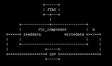
In the system test, a vji_component instance is configured to have an input and output signal of width 24 (by default; the width is configurable). The output signal wires to the input signal through inverters. A tcl script drives random numbers into the writedata port, reads back the inverted signal on the readdata port, and verifies the value. The block diagram shows what's going on (sorry about that "inv" block - my attempt at an ASCII inverter symbol ended in failure).

vji_component_system_test_block.gif

With this new system test, I'm taking the opportunity to create the entire system from as few source files as possible, under control of a Makefile. The system top-level is generated by a europa_module_factory-derived perl module and looks exactly like any other component. (I have come to realize that my use of the word "component" is not standard. When I say "component" I just mean some logic with optional sub-instances. Just about any HDL hierarchy is a "component", so maybe I need a different word.)

The test system source files are as follows:

  • make_quartus_project.tcl: creates the quartus project, makes pin assignments, etc.
  • vji_test_system/vji_test_system.pm: perl module for the system "component". One parameter is provided, "datawidth"
  • compile_quartus_project.tcl: compiles the project in quartus
  • test.tcl: functional test: a script to write, read and verify
  • Makefile: targets are:
    • qp: call a tcl script to create the quartus project
    • hdl: create the HDL
    • sof: compile to bitstream (sof)
    • pgm: program the FPGA
    • test: test the system by writing, reading and verifying
    • clean: destroy the evidence

The upshot of all this: 5 source files encode the system and test scripts. Typing "make" runs everything and reports any errors.

Zip archive of the vji_component and associated tests.

November 25, 2007

Pulse Measurement Testbench

The heart of an IR receive circuit is the pulse measurement circuit. A single-bit signal goes in, and the length of each input pulse goes out. IR-protocol-specific logic to decode the actual data values being transmitted would work off the sequence of length values coming out of the pulse measurement block. The pulse-measurement circuit itself, though, is protocol-agnostic.

Now, I'm planning to build this pulse-measurement circuit (and later on, the follow-on data decode circuit) in firmware in the f2013. I could drive pulses into the f2013 by aiming an IR remote control at the IR transceiver (as seen in VIII. My Little GP1UE267XK) and pushing various buttons on the remote. That sounds pretty annoying - I'd have to pick up and put down the remote all the time, in between typing, and the resulting pulses would vary in length according to factors beyond my control (as I documented in XIII. WWASD?).

Here's a better idea: I'll build logic in the FPGA to generate precise, reproducible pulse sequences, under control of the host PC. Without moving my hands from the keyboard, I'll download various pulse sequences to the hardware, which in turn will drive the device-under-test (f2013 firmware in active development). If I equip the f2013 and testbench logic with a SPI-to-JTAG bridge (as seen in XIV. Hello, world!), then the f2013 can send its interpretation of the pulse sequence back to the host. A script can compare the f2013's report with what was sent - so - a regression test system is possible.

Here's a top-level block diagram of the system:

block.gif

You can see three basic sub-blocks:

  1. VJI: A virtual-JTAG-interface which provides a FIFO-write interface ("source") and an additional signal, "go".
  2. Pulse Gen: The pulse generator proper. The idea here is that the VJI writes a sequence of values into the pulse generator's internal FIFO (data rate limited by the JTAG interface), then asserts the "go" signal, which initiates processing on the FIFO data at top speed. Data read from the internal FIFO specifies the level and pulse duration on the single-bit output, "out".
  3. f2013: The f2013 hardware/software block, which is the real device-under-test here, y'all. The f2013 will measure successive pulse durations and (at least for test purposes) transmit the pulse length values via SPI back to the host.

Notice symmetry: the testbench in XII. Gathering the XBox DVD Remote Codes: Method transformed sequences of pulses from the IR remote into sequences of pulse durations. The new testbench will do the inverse transformation, durations to pulses. I have a big pile of labeled sample data which I collected during the IR remote protocol analysis; I can "play back" the samples to the f2013 firmware as I develop it.

Alright then. For the implementation, I'll generate the entire FPGA system (quartus project, pinout declarations and HDL) via script, relying heavily on europa_module_factory. The next step will be to flesh out the sub-sub-blocks within the VJI and Pulse Gen sub-blocks.

November 14, 2007

avalon_st_error_adapter

An unexpected puzzle came up - a component which seems simple, but turns out to be rather annoying to implement. A good test case, I say. I'll make this quick and brief - the new component files are attached below if you want to dig deeper.

The component's Family/Genus/Species is Adapter/Avalon-ST adapter/Avalon-ST Error Adapter.

Adapter

An adapter, generally speaking, is a simple component which is inserted in between a pair of components of a particular type, to accomplish some sort of conversion. A typical example is the data-width adapter (to allow connection of, say, an Avalon-MM master and slave, or an Avalon-ST source and sink, which happen to have different data widths). A good adapter is fairly simple, does only one thing, and is completely parameterized according to information from the interfaces it connects to.

Avalon-ST Adapter

Adapters of this description are tailored to the particular set of signals supported by Avalon-ST. These adapters understand the specific direction of Avalon-ST signals (e.g. the "data" signal is an output from a source, and an input to a sink; the "ready" signal is an input to a source, and an output from a sink).

Avalon-ST Error Adapter

This adapter does straight-through wiring on all Avalon-ST signals except for one, the "error" signal. All signals other than "error" are required to have the same bit width on both the source and sink which the adapter is connects to. And that's where the regularity ends: the "error" signal is wonderfully free to vary. The source may have no error signal, or a multiple-bit one; likewise on the sink. With mismatched widths, how can the adapter do its job? Well, one more thing about the error signal: each individual bit of the error signal has a "type", which is an arbitrary string, or the special string "other". Given a "type map" for all the source and sink error bits, there are some simple rules for error signal adaptation:

  1. Like-type error bits are directly connected
  2. If the sink has an error bit of type "other", it's driven by the logical OR of any as-yet unconnected source error bits (type "other" or otherwise).
  3. If any undriven sink error bits remain, they are driven with 0.
  4. Any remaining unconnected source error bits are ignored.

Huzzah, a new base class

Since any Avalon-ST adapter will have a mess of same-width signals which wire straight through, and then maybe one signal which needs some special treatment, it makes sense to derive a base class (avalon_st_adapter) from europa_module_factory, from which all Avalon-ST adapters will further derive. This base class calls into a derived class method for doing any special signal handling, then does straight-through wiring on any remaining (non-special) signals. The derived class is concerned only with doing its special job on its special signal(s), and managing any options relevant to the special signal(s).

Command-line args - limited to simple numerals and strings thus far

But that's far too limiting. Here's why: avalon_st_adapter is a component in its own right, though really a silly one. Its generation parameters are a set of signal descriptions (name, width and type) on its "in" (driven by the source) and "out" (driving the sink) interfaces. It's natural to think of these input parameters as a simple pair of hashes, keyed on signal type. But I want to retain the guideline of pure command-line specification of parameters. I could encode those hashes as comma-separated lists of things, to be massaged and processed by a script into proper perl data structures, but that seems like a lot of work. What to do? No problem, I simply pass my hashes in perl syntax on the command line, appropriately escaped, and "eval" does the parsing for me. Validation of these non-scalar fields presents a bit of a nuisance, but nothing that can't be dealt with. For now, I simply validate against the field "type" (HASH, ARRAY, CODE, undef-for-scalar), but nothing stops me from (in the future) defining nested parameter data structures which encode the same sorts of value sets and ranges that I already use for scalar parameters.

To the basic set of port declarations which form avalon_st_adapter's generation parameters, avalon_st_error_adapter adds two more hashes, in which the "in" and "out" interface error bit types are described.

Testing, testing...

Once I had the basic avalon_st_adapter class working, and a skeleton implementation of avalon_st_error_adapter, I found myself doing lots of exploratory refactoring. I worried that I'd break the functionality, which I was happy with. Solution: unit tests. In my case, this means, for each component, a handful of test-case scripts, each of which produces an HDL module, and a top-level test script, "test.sh". After making a change, I run ". test.sh", which runs all the test cases and diffs the output HDL against a set of "known-good" files in a subdirectory. Occasionally, a change is made which does change the output HDL, and for those cases, I carefully examine the new and old files to convince myself that the new HDL file can replace the old known-good one (or note that I've created a new bug, and fix it).

Avalon-ST signal type "error": wonderfully free form

Actually, this is rather an annoying adapter, due to the unconstrained nature of the "error" signal. You'll note that all of the nuisance is concentrated in avalon_st_error_adapter::make_special_assignments().

HDL comments

I went a bit out of my way to produce comments on the adapter assignments, to label the signals and error bit types. Here's a nice ascii block diagram of error adapter test case "3":

avalon_st_error_adapter3.gif

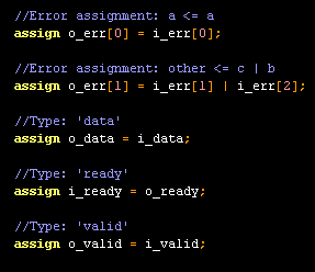
... and here's a snippet of of test case 3's HDL implementation, showing handy assignment comments:

avalon_st_error_adapter3.v.gif

That's it for now. For all my most ardent fans, I'm attaching the new avalon_st_adapter and avalon_st_error_adapter components, along with their test scripts and known-good HDL files. I'm also including the latest version of europa_module_factory, which changed slightly to support the new command-line processing.

components20071114.zip

November 7, 2007

europa_module_factory unveiled

Some results. I've been working up a new framework for authoring HDL modules in Europa, using a simple example component (SPI Slave) as an anchoring point. To present the results, I'll first do a top-down traversal, then dig a bit into the details.

From the top

From the user's point of view, the top level is a simple script, "mk.pl", which invokes the top-level package. This script is not truly a part of the architecture, but it's an easy place to start. Here's the basic call-and-response, at your friendly neighborhood cygwin shell:

[SOPC Builder]$ perl -I common mk.pl

mk.pl:
Missing required parameter 'component'
Missing required parameter 'top'
Missing required parameter 'name'

Usage:
mk.pl [--help]
(Print this help message)

mk.pl --component=<component name> \
        --top=<top level module> \
        --help
(Print sub-package-specific (component::top) help)

mk.pl --component=<component name> \
        --top=<top level module> \
        --name=<top level module name> \
        <component-specific options>
(Create a module of type component::top, with the given name
and options)

A few notes here:

  • "common" is a subdirectory where I've stashed infrastructure perl modules:
    • europa_module_factory.pm: All HDL-module-producing packages derive from this base class.
    • component_utils.pm: You always need one of these. Today it just contains a routine for command-line processing. I expect to throw more stuff in here later.
  • "component" is the overall name of a component (in my example, "spi_slave"). All perl packages for a component are installed in a directory named the same as the component (directory "spi_slave"); all packages are one level down in the hierarchy from the component name (e.g. perl package "spi_slave::control", or "spi_slave/control.pm" in the file system).
  • "top" is the package to invoke as the component top-level. Any sub-package within a component is suitable for top-level invocation, which is handy during development. During ordinary use, there may be several sub-packages which are invoked as the top level.

sub-package-specific help

Here's something cool: component sub-packages must declare their required fields and valid values for those fields. Wouldn't it be handy if sub-package-specific help text were built from that same set of declared required fields? Yes, very handy. Example:

[SOPC Builder]$ perl -I common mk.pl --component=spi_slave \
> --top=spi_slave_mm --help

Allowed fields in package 'spi_slave::spi_slave_mm':
datawidth:
        Data width
        range: [1 .. maxint]
lsbfirst:
        data direction (0: msb first; 1: lsb first)
        range: [0 .. 1]

(By the way, sub-package "spi_slave_mm" is one of the expected top-level packages - it's the SPI Slave component with an Avalon-MM flowcontrol interface.)

How about some help for a less top-level sub-package?

[SOPC Builder]$ perl -I common mk.pl --component=spi_slave \
> --top=fifo --help

Allowed fields in package 'spi_slave::fifo':
datawidth:
        range: [1 .. maxint]
depth:
        allowed values: 1

You can see that this help is less verbose - that's simply because sub-package "fifo" didn't happen to provide descriptions for its fields.

Building an SPI Slave

Help text is swell, but what does a successful component build look like? A few more -I includes are required; a Makefile helps keep things tidy:

[SOPC Builder]$ make
perl \
  -I $QUARTUS_ROOTDIR/sopc_builder/bin \
  -I $QUARTUS_ROOTDIR/sopc_builder/bin/europa \
  -I $QUARTUS_ROOTDIR/sopc_builder/bin/perl_lib \
  -I ./common \
  mk.pl \
          --component=spi_slave \
          --top=spi_slave_mm \
          --name=spi_0 \
          --target_dir=. \
          --lsbfirst=0 --datawidth=8

I've set a name for the top-level HDL file (spi_0), and specified a target directory in which to generate. Parameters "lsbfirst" and "datawidth" are passed along to the chosen subpackage, "spi_slave::spi_slave_mm".

Generator Innards

The basic inner loop of a generator sub-package looks something like this:

# construct an instance of a sub-package module-factory, for example:
my $tx = spi_slave::tx->new({
  lsbfirst => 0,
  datawidth => 13,
});
# ask the module-factory for an HDL instance, and it to the module: 
$module->add_contents(
  $tx->make_instance({
    name => "the_tx",
  }),
);

Besides factory-generated instances, the sub-package will add simple logic of its own to the module.

SPI Slave Results

The new SPI Slave component occupies 32 LEs in my example system (tb_8a), and functions just as the old SPI component did (the old component occupied 40 LEs). The new component is heavily modularized; individual module tend to be very simple. The module hierarchy of the component is in 3 levels:

  • spi_slave_mm
    • spi_slave_st
      • av_st_source
      • av_st_sink
      • control
      • fifo (rx_fifo)
      • fifo (tx_fifo)
      • sync
      • rx
      • tx

The simplicity of this component hides some of the power of the europa_module_factory architecture. It turns out that only a single factory instance is created by each sub-package of the SPI Slave, and in only one case (sub-package "fifo") does an factory deliver more than one HDL instance; in general, though, a single sub-package will create multiple factory instances, which in turn will deliver multiple HDL instances.

By the way, that middle level, spi_slave_st, is a perfectly viable top-level component all on its own, assuming you'd like an Avalon-ST sink and source, rather than an Avalon-MM slave with flow control. This highlights what I believe is a major feature of the architecture: hierarchy comes "for free". Any perl package (and likewise, HDL module) can be instantiated within another. The way is clear to create deeply-nested design hierarchies composed of reusable blocks. It's also possible to build complete systems of components and interconnect, all within a single running perl process. But possibly the most common use of hierarchy will be to add a small amount of functionality to an existing component, by wrapping that component in another layer.

Here's an archive of the component factory modules, spi slave modules and Makefile/build script.

October 6, 2007

Ground Rules

Some rules!

So, I'll be writing perl scripts which will generate HDL for me. Perl is wonderfully flexible, which means there are an unwonderfully infinite numbers of ways to proceed from here. Let's see if I can trim down the possibilities a bit with some goals...

  • Goal: components are generated from the command line by a top-level script, "mk.pl"
  • Goal: any point in the HDL hierarchy is a valid entry point for generation, so that sub-trees of the HDL hierarchy can be generated in isolation

... and guidelines:

  • Guideline: make one top-level perl package per component
  • Guideline: the top-level perl package creates the top-level module. HDL submodules are created by subpackages. All packages define and manage their particular HDL module (or family of closely-related modules) and deliver instances of modules
  • Guideline: sub-package API should be the same as top-level package API, so that submodules can be generated in isolation
  • Guideline: hide as much Europa or other clutter away in base classes; as much as possible, perl modules should consist primarily of code related to their own modules and any sub-instances

... but I don't mean...

It might sound like I'm saying that the perl package hierarchy should reflect the HDL hierarchy. Not so; in fact, this is not possible in general. To understand why, consider the fact that instances of a particular module may appear at various places within the HDL hierarchy. I'll just place all of my subpackages one level down from the top-level package in the package hierarchy; in the file system, package foo (foo.pm) and subpackage foo::bar (bar.pm) will reside in subdirectory foo.

I expect a payoff!

Related note: why bother with all these subpackages? I see these potential payoffs for the added complexity:

  • Code reuse. Occasionally, a sub-entity (package/module) of general utility will appear. This sub-entity can be promoted to a common repository, where it can be shared among all components
  • Separate name-spaces. An immediate payoff here: every package, top-level or sub-level, implements the same API for delivering modules and instances.

With sadness, a confession

For my Europa-generated modules, I would like to think in terms of two possible forms of parametrization:

  1. Generation-time parameters: these parameters modulate the form of the HDL module definition. Each differently-parametrized module is defined as a separate HDL module. There is no limit to the degree of parametrization available, so the challenge is to keep parametrization scope within reasonable bounds. (If a parameter's value results in radically different HDL, it probably makes sense to split into multi subpackages, perhaps sharing a common utility library.)
  2. Instantiation-time parameters: HDL parameters are declared within a module, with a default value; each instance of the module can override the parameter value. This form of parametrization is limited to very simple features, such as port width. It's probably a good idea to use this form when possible, to reduce the total number of modules and improve human readability.

The two types of parametrization are orthogonal: a module may have no parametrization, generation-time parametrization only, instantiation-time parametrization only, or both types of parametrization.

Unfortunately, Europa (as it stands today) does not handle instance-time parametrization very well. In particular, the most obviously-useful form of instance-time parameterization, parameterizable port widths, is not supported. So, I'm forced to fall back upon generation-time parametrization even for simple port width parameters.

So what does it look like?

The nucleus of the implementation is a perl package, europa_module_factory, which defines the base class. Subclasses of europa_module_factory are responsible for producing families of modules grouped by generation-time parametrization. Each subclass implements the following methods:

  1. get_fields: a static method which returns a data structure listing the module's generation options and their legal values. Values are verified against the specified legal range in the (autoloaded) setter methods in the base class. (I expect to add a few more validation types beyond the initial offering, "range". List of allowed values and code reference are natural candidates).
  2. add_contents_to_module: the real meat of the generator: adds all the logic that implements the module's function.

This is sounding much more abstract than it actually is, so it's time for a simple example. The sub-block of the SPI slave, "rx", is a simple shift register with serial input, parallel output and a couple of control signals. There are two generation options, "lsbfirst" and "datawidth". Here's its perl module, rx.pm:


package spi_slave::rx;
use europa_module_factory;
@ISA = qw(europa_module_factory);

use strict;

sub add_contents_to_module
{
  my $this = shift;
  my $module = $this->module();

  my $dw = $this->datawidth();

  $module->add_contents(
    e_register->new({
      out => "rxbit",
      in => "sync_MOSI",
      enable => "sample",
    }),
  );

  my $rxshift_expression;
  if ($this->lsbfirst())
  {
    my $msb = $dw - 1;
    $rxshift_expression = "{rxbit, rxshift[$msb : 1]}";
  }
  else
  {
    my $msb2 = $dw - 2;
    $rxshift_expression = "{rxshift[$msb2 : 0], rxbit}";
  }

  $module->add_contents(
    e_register->new({
      out => {name => "rxshift", width => $dw, export => 1,},
      in => $rxshift_expression,
      enable => "shift",
    }),
  );
}

sub get_fields
{
  my $class = shift;

  my %fields = (
    datawidth => {range => [1, undef]},
    lsbfirst => {range => [0, 1]},
  );

  return \%fields;
}

1;

How to invoke that perl module? A simple Makefile and top-level generation script (mk.pl) handle the grunt work. The command line is:


make COMPONENT=spi_slave FACTORY=rx NAME=rx_0 \
  OPTIONS="--lsbfirst=1 --datawidth=8"

And the resulting HDL (with a bit of boilerplate removed) is:


//Module class: spi_slave::rx
//Module options:
//datawidth: 8
//lsbfirst: 1
//name: rx_0

module rx_0 (
              // inputs:
               clk,
               reset_n,
               sample,
               shift,
               sync_MOSI,

              // outputs:
               rxshift
            )
;
  output  [  7: 0] rxshift;
  input            clk;
  input            reset_n;
  input            sample;
  input            shift;
  input            sync_MOSI;
  reg              rxbit;
  reg     [  7: 0] rxshift;
  always @(posedge clk or negedge reset_n)
    begin
      if (reset_n == 0)
          rxbit <= 0;
      else if (sample)
          rxbit <= sync_MOSI;
    end

  always @(posedge clk or negedge reset_n)
    begin
      if (reset_n == 0)
          rxshift <= 0;
      else if (shift)
          rxshift <= {rxbit, rxshift[7 : 1]};
    end
endmodule

A nearly-identical invocation generates the SPI component top-level:


make COMPONENT=spi_slave FACTORY=spi_slave NAME=spi_0 \
  OPTIONS="--lsbfirst=1 --datawidth=8"

Save some for later

Thoughts for future work:

  • The perl modules I've produced form a thin, porous layer on top of the europa library. "Thin", because they don't provide a lot of complex functionality; "porous", because clients of my perl modules still work with europa objects (e_project, e_module, e_register, e_assign, et al ) directly. It might be worthwhile to try to make an opaque layer on top of europa, for simplicity and possible future reimplementation of the underlying europa code.
  • I have a framework for generated-module-specific validation, with the module options as input. This is good and useful, as it guards against bogus input at the earliest possible time. I'd like to think about how to guard against bogus output (basic sanity tests on the instantiated logic), as well. For example, a module could declare (in some way) its expected input and output ports, and after contents are added, the module could be tested against the expectation. Or, the generated HDL could be parsed by some external tool, from within the generator - this would probably need to be a default-off option, in the interest of speedy generation time.
  • I need to think more carefully about module names. In the current implementation, if multiple instances of the spi_slave component are created, each will have its own (not-necessarily-identical) module called "spi_slave_fifo". One way out of this is to decorate module names with the (unique) name of the top-level instance; this can lead to multiple module declarations identical except for name, but it may be the only practical solution.

For the curious, I attach the complete set of files for the spi_slave and underlying europa_module_factory, as of this moment. The SPI slave is not yet complete, but has a top-level module and two sub-modules for illustration.

October 3, 2007

A Little Chat about Verilog & Europa

Say, what's in my FPGA? Just a sea of configurable wires, registers, and logic. Without a configuration bitstream, the FPGA does nothing (well, it eagerly awaits a bitstream. It does almost nothing.) How do I create that bitstream? Assuming I have some digital logic function in mind, I have only to translate my design intent into one of a handful of gratuitously cryptic hardware-description "languages" and throw it in Quartus' lap. Among my choices are:

  • block diagrams full of little schematic symbols
  • Verilog
  • VHDL
  • an Altera-created hardware description called AHDL

But I eschew all that for a different Altera creation: a collection of perl modules called Europa.

First, the history. Long ago, some clever engineers needed to wire a little soft-core CPU to its UART, onchip memory, PIOs and other peripherals. They could have just banged out a Verilog description of the interconnections and called it a day, but that was too easy. Also, what if someone wanted eleven UARTs? What if they somehow thought VHDL was better? Then what? Clearly, automatic generation of the interconnect bus was indicated, and while we're at it, go ahead and generate the HDL for the UART and PIO as well. What better language in which to write a generator program than Perl? Case closed.

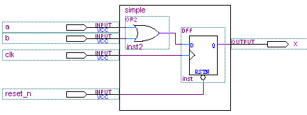
Time for a simple example. Consider the following logic, displayed in a format which still, for me, resonates deeply:

simple_circuit.gif

(I hope the notation is clear: the diagram shows a module named simple, which has some inputs, an OR gate, a D-flip-flop, and an output.)

Module simple translates fairly readily to Verilog:

module simple(
  clk,
  reset_n,
  a,
  b,
  x
);
  input clk;
  input reset_n;
  input a;
  input b;
  output x;

  wire tmp;
  assign tmp = a | b;
  reg x;

  always @(posedge clk or negedge reset_n)
    if (~reset_n) x <= 1'b0;
    else x <= tmp;

endmodule

Even in this extremely simple example, you can see Verilog's flaws. The module's inputs and output are listed twice: once in the module port list and again as input and output declarations within the module. A different sort of redundancy exists between a given signal's direction (as input, output or neither - internal) and its role in the described logic (signal with no source, signal with no sink or signal with both source and sink). Here's the Europa equivalent of the above Verilog, which solves those problems:

use europa_all;

my $project = e_project->new({
  do_write_ptf => 0,
});

my $module = e_module->new({name => "simple"});
$module->add_contents(
  e_assign->new({
    lhs => "tmp",
    rhs => "a | b",
  }),
  e_register->new({
    out => "x",
    in => "tmp",
    enable => "1'b1",
  }),
);

$project->top($module);
$project->output();

The benefits are clear:

  • redundancy is eliminated
  • Perl is a real programming language, and fun besides
  • Even in this simple example, fewer bytes/keystrokes are required to encode the design
  • I didn't show it here, but VHDL output is available (controlled by an e_project setting)

So there you have it. I can merrily go off and build my SPI slave component in Europa, and generate to the HDL of my choice. Great!

However! I couldn't very well count myself among the top 1 billion software architects on the planet if I just went off and coded my component as pages and pages of formless Perl/Europa. No, no, no. I must first make class hierarchy diagrams, invent some directory structure guidelines, and worry about names of API methods. That's the key to success in this business.

Side-note/tangent/rant: there is an alternate Verilog style for coding combinational logic which would prefer the following for the tmp assignment:

  reg tmp;
  always @(a or b)
    tmp = a | b;

I think most programmers would report a long list of flaws in this style. For myself, I find that:

  • It doesn't do what it says: tmp is declared as a "reg", but is purely combinational
  • It's redundant: inputs to the expression must be declared in the "sensitivity list" (a or b), and appear again in the actual assignment (tmp = a | b)
  • It's too big: the superfluous 'always' block consumes more screen area, and requires more typing
  • It reveres historical baggage: Verilog began life as a simulation language; the construct above appears to be informed by that history, to the detriment of the goal at hand (to concisely define digital logic on a programmable chip)

That said, I admit (to my astonishment) that the above is a preferred coding style in the industry. Not a problem: in the end, the precise style of Verilog coding is irrelevant, because (in my so-humble opinion), if you're coding in Verilog, you've already made the wrong choice. So let's not fight this fight: we can leave Verilog style issues to the language lawyers, the guardians of legacy code bases, and those evil-doers with a vested interest in seeing that HDL coding remains a black art.

September 30, 2007

Block Diagrams? Well, Block Descriptions.

I don't have a usable block diagram editor. I tried Microsoft Paint, but it's too bitmap-oriented. I have used Quartus successfully for simple diagrams, but it's not very flexible. I think I achieved the limit of the ASCII block diagrams a while back. So, for now, I'll describe my blocks in words. If anyone has a suggestion for a free and decent block diagram editor, please let me know!

Here are the sub-blocks of the SPI Slave implementation, which will map directly to HDL modules:

  • sync: this block synchronizes the SPI input signals to the system clock domain. Nothing fancy here; just the traditional chain of 2 flip flops, which I use as a magic talisman to ward off metastability.
  • sequencer: From the synchronized SCLK signal (sync_SCLK), this block produces two active-high event triggers:
    1. shift: enable a shift on the outgoing data shift register
    2. sample: enable a sample of the incoming data
    (If I wanted to create a CPOL- and CPHA-configurable slave, this block is the only one that would change.)
  • bit_counter: for a n-bit SPI slave, this block counts from 0 to n-1, incrementing once for each shift. Its outputs control some FIFOs (see below). Inactive level (high) on SS_n resets this counter to 0.
  • rx: MOSI feeds an n-bit shift-register chain, enabled by shift.
  • rx_fifo: A basic FIFO with clk, write, writedata, read, readdata, full and empty signals. When not empty, readdata is valid. For this FIFO, writedata is the rx shift-register chain. For now, this FIFO has a single storage element - call it a receive holding register, if you like. In the future, more FIFO locations may be useful; if so, this block's interface need not change.
  • av_st_source: input is the rx_fifo outputs; output is a standard set of signals implementing an Avalon ST source. This block is just wires.
  • tx: a parallel-loadable shift register. The shift-register output drives MISO directly.
  • tx_fifo: Another FIFO. This one drives the parallel-load input on tx, and accepts data from the Avalon-ST sink or Avalon-MM interface.
  • av_st_sink: another just-wires block. Avalon-ST is pretty much designed to bolt up directly to FIFOs, and this one connects to tx_fifo.
  • av_mm_slave: this optional block funnels the Avalon-ST interfaces into a single Avalon-MM slave interface with flow control (readyfordata, dataavailable). It'll take some careful thought to avoid deadlock on this interface. The lock-step full-duplex nature of SPI will be a key factor in this.

That seems like a lot of blocks! Fortunately, though, most of them are very very simple.

Next, I'll get to dig into the implementation. I'll probably need to say some introductory words about Europa, first.

A Note on Clock-Domain Crossing

I've made the choice to synchronize the SPI input signals as they enter the FPGA; all logic in the SPI slave will be in the system clock domain. Delaying the SPI signals like this implies an upper bound on the SCLK frequency, relative to the system clock rate (I think the max SCLK will be something like 1/4 the system clock frequency). There is another option: SCLK could drive a subsection of the SPI slave, all the way from serial input to parallel output. The parallel output would connect to proper clock-crossing FIFOs. This solution would be more complex, but should be able to run at a higher clk/SCLK ratio. I won't implement this solution for now, but it's worth keeping in mind if higher bandwidth is needed.